INDUSTRIAL PUMPS FOR UNLOADING TRUCKS

APPLICATION: CHEMICAL PUMPS TO UNLOAD TANKER TRUCKS AND RAILROAD TANK CARS

GemmeCotti supplies industrial pumps suitable to unload railroad tank cars and tanker trucks containing acids and toxic chemicals.

truck-unloading-h-ibc

We offer three possible solutions for this application:

  • installation of one pump for each single tank
  • installation of the pump directly aboard the vehicle (GemmeCotti series HTM or series HCO)
  • use of the portable pump H-IBC (GemmeCotti series HTM 10)

SPECIFIC REQUIREMENTS FOR THIS APPLICATION: WHICH ARE THE BEST PUMPS FOR TANKERS OFFLOADING?

The right pumping solution for unloading and transferring dangerous liquids from vehicles (trucks or railroad tank cars) is selected according to the chemical compatibility and the requested performances.

GemmeCotti pumps are the best choice to transfer dangerous or hazardous goods, i.e. all the substances which, due to their peculiar properties, could be harmful for the environment or the people involved.

These liquids are classified according to their characteristics and degree of danger. In Europe, the transportation of toxic chemicals is regulated by specific laws:

  • ADR: agreement concerning the international transport of dangerous goods by road
  • RID: international carriage of dangerous goods by railrailroad-tank-cars
  • ADN: carriage of dangerous goods by inland waterways

GemmeCotti is proud to offer pumping solutions for the safe handling of chemicals: we supply chemical pumps suitable for the safe offloading of the great majority of dangerous or hazardous goods.

Fluids generally involved in this application:

  • ammonia
  • sulphuric acid
  • nitric acid
  • hydrochloric acid
  • sodium hydroxide (caustic soda)
  • hydrogen peroxide

…and many more!

Check the chemical compatibility guide

WHICH IS THE BEST TYPE OF PUMP TO CHOOSE?

The GemmeCotti pumps installed on means of transport and involved in the unloading process, permit to direct and move the fluids in total safety, ensuring quick execution.

For this application, GemmeCotti recommends:

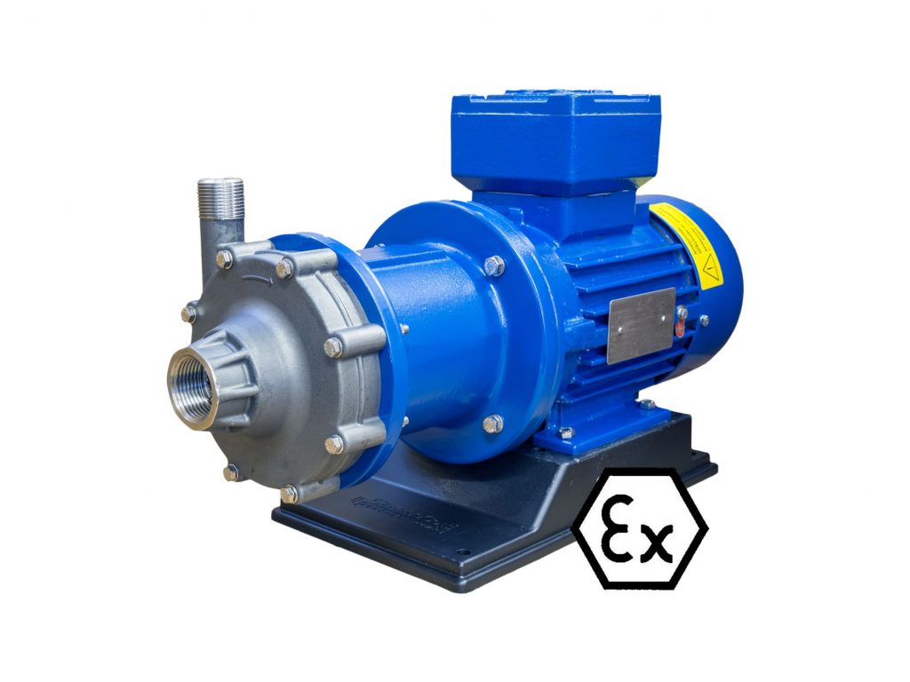
  • magnetic drive centrifugal pumps series HTM PP/PVDF
  • mechanical seal centrifugal pumps series HCO

The design of these two types of centrifugal pumps, permits the safe installation both on land and aboard the vehicle, ensuring a constant flow without the risk of leakage or emissions.

Magnetic pumps series HTM PP/PVDF

Mechanical seal pumps series HCO

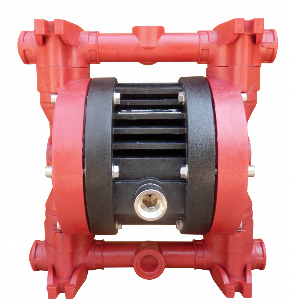
Another practical and effective solution is the use of the GemmeCotti portable pump series H-IBC.

gemmecotti-h-ibc-pumps-

GemmeCotti H-IBC has been designed as a safe and reliable mobile pump specifically for the safe unloading of IBC containers. The unit consists of a magnetic centrifugal pump HTM 10 mounted in a robust carry case, conceived to be easy to move. Thanks to its fast connections, H-IBC is a really flexible solution: the pump could be easily removed from the IBC container and placed in another one according to the requirements. This quick and efficient unit is suitable for several applications. Moreover, the pump is equipped with an electric panel and a start and stop switch for easy, quick and safe use.

Upon request, H-IBC pumps can be supplied in a premium version with wheels, for easier movement and transportation.view-h-ibc

Learn more about our portable pumps H-IBC series

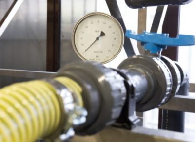
HOW TO AVOID THE RISK OF DRY RUNNING DURING THE PROCESS OF TANKERS UNLOADING?

To prevent damages to the pumps due to the lack of liquid, GemmeCotti supplies the dry running protection device. This device is particularly recommended during the operations of tanker unloading and for all the applications in which there is the risk of liquid shortage.

Thanks to the adjustable threshold and timer, it is possible to set up the minimum power and operation time of the device. If the power is lower than the set value, the pump will automatically stop.

Main features of the dry running protection device:

Dispositivo contro la marcia a secco - dry running protection device

Single Phase CURRENT RELAY

Multirange 15-35A

2 set points MAX / min

Also for motors with INVERTER


More information about the device 

MAGNETIC DRIVE CENTRIFUGAL PUMPS AND MECHANICAL SEAL PUMPS

It is fundamental to choose the right pump model when dealing with acids or corrosive liquids. For theGemmeCotti HTM e HCO chemical pumps operations of tanker unloading, GemmeCotti suggests the use of mechanical seal centrifugal pumps or magnetic centrifugal pumps. The type of pump is selected according to the liquid to be pumped and to the requested working point.

MAGNETIC DRIVE CENTRIFUGAL PUMPS

Mag drive pumps have a sealless design that is particularly suitable to pump corrosive and dangerous liquids; the magnetic design together with the usage of anticorrosive materials, guarantees the high chemical resistance and the absence of leakage and emissions.

Moreover, the structure of magnetic drive pumps is really simple and requires very little maintenance with a consequent saving in terms of repairs and spare parts expenses during the pump life. The external magnet placed on the drive shaft transmits the motion to the internal magnet connected to the impeller, which rotates and moves the fluids through the pump.

MECHANICAL SEAL PUMPS

Mechanical seal centrifugal pumps are the best solution when the liquid has solids in suspension: their design with open impeller permits to transfer dirty liquids and fluids with high viscosity.

The seal of these pumps is composed of a static ring and a rotating ring placed on the pump shaft, which is directly coupled to the motor shaft. When the pump is working, the two rings’ surfaces slide together and the lubrication of the parts is granted by the pumped liquid.


GemmeCotti supplies pumps for chemicals suitable for the offloading process of tanker trucks, petrol tankers and railroad tank cars. Our industrial pumps allow you to unload the fluids with the maximum efficiency, ensuring safety, reliability and saving in terms of repairs and spare parts expenses.

Upon request, GemmeCotti pumps can be supplied with single phase motors and in ATEX version for potentially explosive areas.


Contact us: info@gemmecotti.com


Our sales department is available from Monday to Friday, from 8.30 to 12.30 and from 12.30 to 14.00, to select the best chemical pump for your needs.

Read More

INDUSTRIAL PUMPS FOR BIG AQUARIUMS: APPLICATIONS WITH FRESHWATER AND SEAWATER

APPLICATION: THE PUMPING SYSTEM OF BIG AQUARIUMS

The fish tanks of big aquariums allow the public to admire many fascinating underwater creatures. Through hundreds of windows the enchanted visitors look at the wide variety of plant and animal species which populate lakes, rivers and oceans of the planet.

Aquarium pumps

The invisible and complex pumping system of big aquariums permits the survival of aquatic species in freshwater and seawater inside the exhibition tanks. The circulation and filtration of the water is possible thanks to the pumps which direct the liquid through the filter before returning it to the tanks.

The pumping system must guarantee the quality of the water by maintaining its main chemical and physical properties in order to recreate the natural habitat of the aquatic flora and fauna.

The pumps used in these giant freshwater and saltwater aquariums must be corrosion resistant and able to pump large amounts of liquid. Moreover the pumps must be silent to avoid the risk of creating a stressful situation that could alter the normal fish behaviour.


SPECIFIC REQUIREMENTS FOR THIS APPLICATION: WHICH ARE THE BEST PUMPS FOR APPLICATIONS IN BIG AQUARIUMS PUMPING SYSTEMS?

Pumps made of thermoplastic materials are recommended for large systems pumping saltwater or freshwater.

The thermoplastic materials used in the manufacture of GemmeCotti pumps are solid and lightweight and they don’t absorb water. Certainly, the best material for the construction of saltwater pumps is polypropylene (PP), a thermoplastic polymer with a good thermal, mechanical and abrasive resistance.

The use of this anti corrosion material, instead of the installation of pumps in metallic materials, avoids the risk of dispersion of metallic particles, which could harm the health of the sea fauna.

WHICH IS THE BEST TYPE OF PUMP TO CHOOSE?

Centrifugal pumps are the best choice for freshwater and seawater aquariums.

A centrifugal pump is made of a movable part called the impeller that forces the liquid under pressure in a desired direction.

GemmeCotti HTM 10 PP centrifugal pump

MAGNETIC DRIVE CENTRIFUGAL PUMPS

Centrifugal pumps can be designed with a particular system called magnetic drive.

Mag drive pumps have a sealless design that is particularly suitable to pump corrosive and dangerous liquids; the magnetic design together with the usage of anticorrosive thermoplastic materials, guarantees the high chemical resistance and the absence of leakage and emissions. Thanks to the total absence of emissions and leakage, the plant will always be clean; this feature coupled with the reduced maintenance required by GemmeCotti pumps, helps in keeping the plant efficient, secure and reliable.

The structure of magnetic drive pumps is really simple and requires very little maintenance with a consequent saving in terms of repairs and spare parts expenses during the pump life.

The use of mag drive centrifugal pumps in thermoplastic materials, such as GemmeCotti pumps series HTM PP/PVDF, is the best solution for working with fresh water and sea water. In particular, the smallest models of this series (HTM 4, HTM 6, HTM 10) are particularly recommended for the pumping system of big aquariums.


Check the technical data and download the complete catalogue!


Read More

HAOD PNEUMATIC PUMPS: RELIABILITY AND VERSATILITY

GemmeCotti supplies air-operated double diaphragm pumps suitable to transfer aggressive liquids with high viscosity and solids in suspension.

HAOD air-operated double diaphragm pumps

The main feature of HAOD pumps is their versatility: these volumetric self-priming pumps are suitable for applications in chemical and pharmaceutical industries and in water treatment plants. Moreover HAOD pumps are commonly used in dosing systems and they are usable for trucks or barrels.


HAOD pneumatic pumps installation


HAOD assure high pressures and high heads in addition to the compatibility with a wide selection of liquids. HAOD pumps are built with an anti-stalling pneumatic circuit which ensures the highest possible level of security and efficiency and doesn’t require lubricated air: the ecological design guarantees a reduction in the air consumption.
Moreover, HAOD are fast and easy to assemble without the use of special tools.

HAOD pneumatic pumps are available in several materials and dimensions: diaphragms are made of PTFE while the pump body can be manufactured in thermoplastic materials (PP or PVDF) or metallic materials (stainless steel AISI 316).

Air-operated double diaphragm pumps are available in ATEX version for potentially explosive atmosphere classified zone 2 II3G.


MAIN FEATURES:

• Available in PP, PVDF and AISI316;
• Max. Temperature:
PP: 60° C – PVDF: 95° C – AISI 316: 95°;
• Adjustable capacity and head;
• Adjustable speed without pressure loss.

OPTIONAL:
• Pulsation damper.


CHECK THE TECHNICAL DATA AND DOWNLOAD THE COMPLETE CATALOGUE!

Read More

GEMMECOTTI ATEX PUMPS: THE EM SERIES

GemmeCotti supplies ATEX pumps for potentially explosive atmospheres. Our ATEX EM series are suitable for ZONE 1 II2G and ZONE 2 II3G classified areas.

What does ATEX stand for? 

ATEX is an abbreviation for the French term “ATmosphères EXplosibles“, which translates to “Explosive Atmospheres” in English.   It refers to the European Union’s directives for regulating equipment and protective systems intended for use in potentially explosive atmospheres. These directives aim to protect workers from the risks associated with explosive environments.

What is the ATEX standard for the EU?

The ATEX standard for the EU is actually a set of directives that aim to protect workers from explosion risks in hazardous environments. There are two main directives, all our pumps comply with the technical and safety requirements of ATEX Directive 2014/34/EU
The Directive states that the manufacturers of equipment intended for use in potentially explosive atmospheres shall draw up a written declaration of conformity of these products.

How are the ATEX Zones classified?

The term “ZONE 1” indicates an area where an explosive atmosphere consisting of a mixture of air or flammable substances (gas, vapour or mist) is likely to occur in normal operation occasionally.

The term “ZONE 2” indicates an area where an explosive atmosphere consisting of a mixture of air and flammable substances (gas, vapour or mist) is not likely to occur in normal operation. If it does occur, it will persist for a short period only.


What does GemmeCotti offer for potentially explosive atmospheres?

GemmeCotti ATEX pumps for potentially explosive atmospheres EM series includes 3 metallic pumps (AISI 316) and 6 plastic pumps (PP/PVDF).

ATEX PUMPS made of stainless steel AISI 316 suitable for ATEX ZONE 1 II2G and ZONE 2 II3G:

EM-C Atex centrifugal mag drive pumps:
Max flow 32 m3/h, max head 24 mlc
EM-P Atex rotary vane mag drive pumps:
Max Flow 2100 l/h, max head 13 bar
EM-T Atex turbine mag drive pumps:
Max Flow 7 m3/h, max head 78 mlc

GemmeCotti ATEX pumps in AISI 316

ATEX PUMPS made of plastic materials PP/PVDF suitable for ATEX ZONE 2 II3G:

EM-C PP-PVDF Atex centrifugal mag drive pumps:
Flow up to 130 m3/h, head up to 48 mlc
EM-C SP PP-PVDF Atex centrifugal mag drive pumps:
Flow up to 25 m3/h, head up to 22 mlc
EM-T PP-PVDF Atex turbine mag drive pumps:
Max capacity: 9 m3/h, max head: 50 mlc
EM-P PP-PVDF Atex vane mag drive pumps:
Max flow: 1000 l/h, max pressure 5 bar
EM-T SP Atex turbine self-priming pumps:
Max flow: 6 m3/h, max head 24 mlc
EM-CO Atex mechanical seal pump:
Flow up to 58 m3/h, head up to 38 mlc

GemmeCotti ATEX pumps in PP/PVDF

ALL THESE ATEX PUMPS ARE SUITABLE TO TRANSFER:

  • Acids and bases
  • Corrosive, toxic and dangerous liquids
  • Hydrocarbons, pyrophorics and other flammables
  • Heat transfer oils
  • Refrigerants and cryogenics
  • Radioactive liquids

Our ATEX pumps are suitable for various applications and they are supplied with the ATEX certificate for ATEX ZONE 1 and 2.

You should specify the ATEX zone in your enquiry, our sales office will select the right pump according to your requirements.

All the pumps include the required protective systems.

Read More
how to select a pump - parameters

Pump selection guide: all the parameters

Selecting an industrial pump for acids is a critical engineering decision that goes far beyond simply transporting fluids. A meticulous selection process is essential to ensure operational reliability, process efficiency, system longevity, and, above all, safety. Choosing the wrong pump can lead to premature failures, costly downtime, inefficient energy consumption, and potentially hazardous situations. This guide provides an analysis of the essential technical parameters to consider when selecting the most suitable pump for your needs.

Part 1: fluid characteristics

The fluid itself dictates most of the pump selection criteria. Its physical and chemical properties will determine the appropriate materials of construction, the type of pump required, and the power needed to move it.

1.1 Chemical composition and corrosivity

The first step is to identify every chemical component of the fluid. This analysis is crucial for selecting materials that can withstand corrosion, degradation, and chemical attacks.

  • Materials of construction: The choice between metals (e.g., Stainless Steel 316), thermoplastics (e.g., PP, PVDF), and elastomers (e.g., EPDM, FKM, FFKM) depends entirely on chemical compatibility.
  • Purity requirements: Applications in sectors such as pharmaceuticals or food may require specific materials (e.g., FDA-compliant) to prevent fluid contamination.

GemmeCotti specializes in this field, offering a wide range of pumps for acids and hazardous liquids made from thermoplastic (PP and PVDF) and metallic (Stainless Steel 316) materials. To select the right material for the pump, GemmeCotti technicians rely on over 30 years of know-how in the chemical pump field and compatibility charts from authoritative sources. To get an idea of material compatibility with the most common liquids, you can refer to the chemical compatibility guide.

1.2 Fluid viscosity

Viscosity is a measure of a fluid’s resistance to flow. It is one of the most critical parameters affecting pump selection and performance.

  • Centrifugal pumps: These are highly efficient for low-viscosity fluids (e.g., water, solvents). However, as viscosity increases, their efficiency drops sharply, and the required motor power rises drastically. Generally, they are not suitable for viscosities above 200 cSt.
  • Positive displacement pumps: These are the preferred choice for viscous liquids (e.g., oils, resins, syrups). They effectively handle higher viscosities, and their flow rate is less affected by viscosity changes.
  • Turbine pumps: This type of pump provides a higher head than centrifugal pumps but can only handle low-viscosity liquids (max 45 cPs).

1.3 Fluid temperature

Temperature affects several parameters:

  • Vapor pressure: Higher temperatures increase a liquid’s vapor pressure, which directly reduces the available NPSH (NPSHa). This increases the risk of cavitation.
  • Viscosity: The viscosity of most liquids decreases as temperature increases.
  • Material limits: Every material has a maximum operating temperature. Exceeding this limit can lead to mechanical failure.

1.4 Specific gravity (SG)

Specific gravity is the ratio of a fluid’s density to the density of water. It does not affect the head a centrifugal pump can produce (expressed in meters), but it directly impacts the pressure generated and the power required.

  • Pressure calculation: Pressure (bar) = (Head (m) * SG) / 10.2
  • Power calculation: The power required by the motor is directly proportional to the fluid’s specific gravity. A fluid with an SG of 1.5 will require 50% more power to be pumped than water, given the same flow rate and head.

GemmeCotti pumps are designed to accommodate different motor powers for the same pump size, allowing them to operate without issues of absorbed power even with high specific gravity liquids.

1.5 Presence and nature of solids

If the fluid contains suspended solids, it is necessary to define:

  • Concentration: The percentage of solids by weight.
  • Particle size, hardness, and shape: Abrasive solids (like sand or metal fines) require hardened materials and specialized pump designs (e.g., slurry pumps with vortex impellers or thick rubber linings) to resist wear. Soft or stringy solids can clog standard impellers, requiring a design specific to the application.

Part 2: System hydraulics – defining the workload

Once the fluid is understood, the next step is to define the system’s hydraulic requirements.

2.1 Required flow rate

This is the volume of fluid that needs to be moved in a given period, typically measured in m³/h, GPM (gallons per minute), or l/s. It is determined by the process needs.

2.2 Head and pressure

To move the fluid through the system, the pump must supply it with energy. This energy is commonly expressed as head. Head is the height to which the pump can push the fluid and is measured in meters of liquid column (m.l.c.) or simply in meters (m).

A fundamental aspect of head is that it is independent of the fluid type: the same pump will lift different liquids, even with different specific gravities, to the same height.

Pressure, on the other hand, is strictly dependent on the fluid’s density. At the same height (head), a column of liquid will exert a different force depending on its specific gravity. Consequently, a pump that generates a certain head will produce different pressures depending on the liquid it is pumping. For example, the pressure generated when pumping water will be different from that generated when pumping oil at the same head.

2.3 Net Positive Suction Head (NPSH)

As detailed in our previous article, a rigorous NPSH analysis is mandatory. You must ensure that your system’s NPSH available (NPSHa) is always greater than the pump’s NPSH required (NPSHr) to prevent destructive cavitation.

To further explore the difference between these two concepts, we have written a dedicated article on this topic: Pump Pressure vs. Head.

Part 3: Environmental and operational factors

The final set of parameters concerns the pump’s installation environment and intended use.

3.1 Installation area (ATEX)

For hazardous environments where flammable gases, vapors, or dust may be present, a pump certified for that specific ATEX zone is legally required to prevent ignition.

3.2 Environmental conditions

  • Temperature and humidity: High ambient temperatures can affect motor cooling and performance. High humidity can lead to corrosion or problems with electronics.
  • Altitude: At higher altitudes, the lower air density reduces the cooling effectiveness of standard fan-cooled motors, often requiring a motor derating.

To summarize, all the essential parameters discussed are laid out in the following table. This provides a checklist of the data and variables required for a correct pump selection. It is crucial to accurately define these values to proceed with the identification of the most suitable pump.

how to select a pump - parameters

Conclusion: A data-driven decision

The pump selection process is a meticulous engineering task that requires a thorough analysis of fluid properties, system hydraulics, and environmental conditions. By systematically evaluating each parameter—from chemical compatibility and viscosity to total dynamic head and ATEX requirements—you can ensure the selection of a pump that is not only effective but also highly reliable, energy-efficient, and safe. This data-driven approach goes beyond mere guesswork, guaranteeing a robust solution that will serve your process effectively for years to come.

For expert assistance in analyzing these complex parameters and selecting the ideal pump for your application, contact our team at info@gemmecotti.com. 


Read More

AODD pumps: 4 reasons to choose diaphragm pumps


AODD pumpsThe AODD pumps, Air Operated Double Diaphragm pumps, appeared in the pump market for the first time about sixty years ago. Thanks to the constant technological improvement, they have managed to set themselves as the best choice for pumping high-viscosity fluids.

There are four reasons why you should prefer a double diaphragm pump as our HAOD pumps for your plant. Here they are:

  1. VERSATILITY AND VARIETY OF APPLICATION

    The AODD pumps find application in a wide range of installations, thanks to their versatility and to their features. For example: the ability to self-prime, the possibility to run dry, the potential to be submersible, and the possibility to pump high-viscosity fluids. Moreover they are available in different materials in order to overcome any problems of fluid compatibility.

  2. DESIGN AND SIMPLICITY

    The design and the ease of use of the AODD pumps are among the reasons they are so appreciated in the chemical pumps market. Indeed they are often described as “plug-in-and-play” or “set-and-forget” pumps, because once installed and connected to a compressed airline they can work for themselves in full autonomy. They can be provided in a multiplicity of dimensions, easily meeting every customers’ needs.

  3. SAFETY AND ECOLOGY

    Thanks to its closed design, the usage of compressed air as the only power source, and its stall-prevention pneumatic system, AODD pumps are one of the safest pumping system for hazardous liquids, together with the mag-drive pumps. Moreover the ecological design of AODD pumps allows them to realize up to 60% saving in air consumption. Thanks to this saving, their impact on environment decreases significantly. Less air consumption means indeed the possibility to use smaller air compressor, with consequent energy and money saving.

  4. MONEY SAVING

    The money saving, especially in the long-period, is amongst the reasons why you should consider to select a diaphragm pump. The improvements made in diaphragms construction have indeed dramatically increased the life of the diaphragm pumps. They can work properly for years with a very low maintenance, especially thanks to their static seals. These seals maintenance indeed tends to be infrequent and inexpensive.

Have we convinced you? Visit the webpage of our HAOD in order to learn more about air operated pumps. For further information contact us at info@gemmecotti.com. Our technical and sale departments will be glad to lead you to the best choice.

Read More

Pressure vs head, what is the difference?

The pump selection of a pump is driven by the following main parameters:
– Head (H)
– Flow rate (Q)
– Fluid characteristics (ρ, γ, T ….)
Sometimes head can be confused with pressure during pump choice. As a matter of fact there is a strict relation between them which is defined by the fluid specific gravity, so the relation is fluid dependent. So what is the difference between pressure and head?

Definition of head and pressure

Head is the height given by the pump to the fluid and it is measured in meters of liquid column [m.l.c.] or simply indicated in meters [m]. The given head is fluid independent: different fluids
with different specific gravities are all lifted at the same height.
Pressure, instead, is fluid dependent and it is affected by the liquid density. In fact the force of a fixed height liquid column over a unitary area will change with different specific gravities. So in this case the same head generates different pressures.

Measurements: Pressure or Head?

Head is not directly measured. Manometers on the pump suction and delivery line give the measure of the pressure. Measurements given by manometers indicate differential pressures imposed by the pump between suction and discharge. These measures are read in [bar] [atm] [psi] [ft H2O] etc.. Specific gravity γ has to be considered to evaluate the correspondent head.

Conversions & Practical Example

As stated before, the same pump at the same working point will give always the same head with different pressures in accordance with the density γ of the working fluid.
For example, a mag drive centrifugal pump HTM 10 working at a given point Q= 7.5 m3/h H = 10 mlc operating with water and concentrated H2SO4 gives the same head (H=10m) to water ( γ= 1kg/dm3) and to sulfuric acid (γ = 1.8kg/dm3), while measurements of differential pressures between suction and delivery will be:

equazione pressione 12

The mathematical relationship is reported in the following equation:

equazione pressione 1
Also power consumption is influenced by the previous relationship of pressure, as:

equazione pressione 2curve pressure

Notes for technicians

– Previous relations are valid for low viscosity fluids (water equivalent), along with increasing viscosity, pump performances have to be reduced using pump derating rules.
– At a fixed rotational speed a centrifugal pump generates head related to the flow rate following its characteristic curve.
– The computation of the needed head that should be delivered by the pump, is not so straight as the evaluation of the desired height difference. Needed Head is composed by the following terms:

  • Geodetic head: difference between suction and delivery height expressed in meters of liquid column

equazione pressione 3

  • Difference between absolute pressure of the delivery and suction reservoir

equazione pressione 4

  • Distributed and concentrated friction losses also expressed in m.l.c.
    equazione pressione 5
Read More

How to read a pump curve

If you are new in the pump field, reading a pump performance curve (usually just called “pump curve”) can be difficult and sometimes confusing. That’s why we want to help you by offering a simple guide for a first approach to a pump curve.

What is a pump performance curve and why do you need to know how to read it?

A pump curve is a graphical representation of the performance of a pump based on the tests of the pump manufacturer. Every pump has its own curve and it varies very widely from pump to pump. The variation depends on many factors such as the kind of pump (centrifugal pump, turbine pump, vane pump etc.), size and shape of the impeller. Pump curves can be used to provide many information of pump performance and absorbed power which are important for a user to determine the working point and motor power and size.

What information can I find on a pump curve?

1- In the simplest and widely used pump curve (commercial multi-pump curve) you can see two vital pump performance factors: flow and head.

The flow or capacity (Q) is measured in m3/second according to the international standards but usually you can find it expressed in m3/h, l/min or gpm (in the US). It is the volume of liquid moved in an amount of time. On the curve below (Picture 1) you can see the flow marked in red on the horizontal axis.

The head (H) is the height at which a pump can raise a liquid up. It is measured in meters (m or mlc meter of liquid column) or feet and you can see it marked in blue on the vertical axis on the picture below.

Pump performance curve with flow and head

PICTURE 1 MULTI-PUMP CURVE 

How can you read this pump curve?

To select the right pump model you should, first of all, identify the capacity and the head needed for  your system.

If you need for example a flow of 15 m3/h at 20 m you can find the right pump curve and consequently the right pump in the intersection of the two red arrows in the chart. In the example below the pump suitable is magnetic drive centrifugal pump model HTM 31.


The curve enables you to see how the pump will perform at any given point within its performance range. For example, the same pump model HTM 31 at 15 m3/h will produce a head of 20 m, or at 24 m of head the pump will generate a flow of 8 m3/h.

Once you have chosen the right pump type whether centrifugal, turbine, vane or any other, you can study in details the specific curve of the selected pump model with other technical information.

2– In picture 2 you can see an example of a centrifugal pump curve (HTM 31 PP/PVDF) with additional details than curve in picture 1 such as for example the impeller diameter (curve A circled in red), the NPSHr (curve B) and the absorbed power (curve C). In some case you can also find the pump efficiency.  This kind of curve is usually used by pump manufacturers to select the correct pump model among their set of performance curves.

Performance curve centrifugal pump

PICTURE 2

How can you read this pump curve?

In the title box at the top you can find the pump model, the number of poles of the motor, the frequency, the RPM and the pump material (selected according to the liquid to pump).

In curve A you can see the flow and head as described in the paragraph above but there is also a reference of the impeller diameter. For this pump model the available impeller diameters vary from a  minimum of   110mm to a maximum of 134 mm. The impeller would be trimmed by the manufacturer to whatever diameter needed to meet your conditions of service. If the impeller selection is 122 mm at a flow of 10 m3/h the head is about 19 mlc. The manufacturer would determine the proper impeller diameter for your conditions and trim it to the correct diameter.

Curve A - centrifugal pump

In curve B you can see the NPSHr of the pump measured in meters or feet in accordance with the capacity required. This is the minimum head at the suction of the pump that allows the pump to work properly. If sufficient NPSH available is not supplied by the plant (NPSHa) the pump will cavitate and this will affect both the performance and the pump lifetime. In case of 10m3/h capacity you have to find the intersection with the curve of the selected impeller diameter and read the value on the left.

Curve B - centrifugal pump

In curve C you can find  the absorbed power required for pumping a liquid with a SG of 1. Once determined the impeller diameter and the flow you can find the intersection where you can read the absorbed power, which is necessary to determine the relevant motor power.

Curve C - centrifugal pump

The correct selection of a pump using a pump curve is essential to permit a proper working of your system. A working point too far out on the curve, or too far back, can cause damage to the pump, excessive energy consumption, poor performance and pump failure.

For further information don’t hesitate to contact us www.gemmecotti.com


Read More

Video: how to assemble and disassemble magnetic drive turbine pump HTT

Here is the new GemmeCotti video tutorial: how to assemble and disassemble magnetic drive turbine pump series HTT PP/PVDF. Enjoy!

MAIN FEATURES OF PUMPS HTT PP/PVDF:

Magnetic drive regenerative turbine pumps series HTT are made of thermoplastic non-metallic materials (polypropylene-PP and PVDF) and are suitable to pump high corrosive and dangerous liquids. Thanks to the innovative sealless mag drive system, pumps model HTT reduce risks of leakage and emissions and the maintenance costs are very low. The transmission of the motion occurs through magnetic joints without any mechanical seal. This design guarantees the maximum safety and efficiency.

Max capascity: 9 m3/h

Max head: 50 mlc

Max temperature: 70°C for PP pumps and 90°C for PVDF pumps

Contact our office for more information: info@gemmecotti.com


Read More

Mag drive pump HTM 31 PP/PVDF now suitable for 4kw

Sealless Magnetic Drive pumps model HTM 31 PP/PVDF are now suitable also for 4 KW motor size 112. This pump model can be coupled to three different motor sizes:

SIZE 90 – 2,2KW
SIZE 100 – 3KW
new SIZE 112 – 4 KW
You can contact our sales department for more details.


What are the characteristics of mag drive pump model HTM PP/PVDF?

HTM PP/PVDF pumps are mag drive centrifugal pumps made of thermoplastic materials (PP and PVDF) and are suitable to pump high corrosive liquids.

Max capacity: 45 m3/h, Max Head: 33 mlc, Max
Temperature: 90°C Max viscosity: 200 cSt, Pressure rating NP 4 at 20°C.

Click here to find out more.


How does a magnetic drive pump work?

Sealless mag drive pumps have a particular sealless design that is suitable to pump corrosive and dangerous liquids thanks to the high chemical resistance and absence of leakage and emissions. The structure is really simple and requires a very reduced maintenance with consequent save in terms of repairing and spare parts costs during the pump life.
The external magnet, placed on the drive shaft, transmits the motion to the internal magnet connected to the impeller which rotates and moves the fluid through the pump.

Here is a sketch of the functioning of magnetic drive system.Mga drive pumps


Read More
Newsletter