how to select a pump - parameters

Pump selection guide: all the parameters

Selecting an industrial pump for acids is a critical engineering decision that goes far beyond simply transporting fluids. A meticulous selection process is essential to ensure operational reliability, process efficiency, system longevity, and, above all, safety. Choosing the wrong pump can lead to premature failures, costly downtime, inefficient energy consumption, and potentially hazardous situations. This guide provides an analysis of the essential technical parameters to consider when selecting the most suitable pump for your needs.

Part 1: fluid characteristics

The fluid itself dictates most of the pump selection criteria. Its physical and chemical properties will determine the appropriate materials of construction, the type of pump required, and the power needed to move it.

1.1 Chemical composition and corrosivity

The first step is to identify every chemical component of the fluid. This analysis is crucial for selecting materials that can withstand corrosion, degradation, and chemical attacks.

  • Materials of construction: The choice between metals (e.g., Stainless Steel 316), thermoplastics (e.g., PP, PVDF), and elastomers (e.g., EPDM, FKM, FFKM) depends entirely on chemical compatibility.
  • Purity requirements: Applications in sectors such as pharmaceuticals or food may require specific materials (e.g., FDA-compliant) to prevent fluid contamination.

GemmeCotti specializes in this field, offering a wide range of pumps for acids and hazardous liquids made from thermoplastic (PP and PVDF) and metallic (Stainless Steel 316) materials. To select the right material for the pump, GemmeCotti technicians rely on over 30 years of know-how in the chemical pump field and compatibility charts from authoritative sources. To get an idea of material compatibility with the most common liquids, you can refer to the chemical compatibility guide.

1.2 Fluid viscosity

Viscosity is a measure of a fluid’s resistance to flow. It is one of the most critical parameters affecting pump selection and performance.

  • Centrifugal pumps: These are highly efficient for low-viscosity fluids (e.g., water, solvents). However, as viscosity increases, their efficiency drops sharply, and the required motor power rises drastically. Generally, they are not suitable for viscosities above 200 cSt.
  • Positive displacement pumps: These are the preferred choice for viscous liquids (e.g., oils, resins, syrups). They effectively handle higher viscosities, and their flow rate is less affected by viscosity changes.
  • Turbine pumps: This type of pump provides a higher head than centrifugal pumps but can only handle low-viscosity liquids (max 45 cPs).

1.3 Fluid temperature

Temperature affects several parameters:

  • Vapor pressure: Higher temperatures increase a liquid’s vapor pressure, which directly reduces the available NPSH (NPSHa). This increases the risk of cavitation.
  • Viscosity: The viscosity of most liquids decreases as temperature increases.
  • Material limits: Every material has a maximum operating temperature. Exceeding this limit can lead to mechanical failure.

1.4 Specific gravity (SG)

Specific gravity is the ratio of a fluid’s density to the density of water. It does not affect the head a centrifugal pump can produce (expressed in meters), but it directly impacts the pressure generated and the power required.

  • Pressure calculation: Pressure (bar) = (Head (m) * SG) / 10.2
  • Power calculation: The power required by the motor is directly proportional to the fluid’s specific gravity. A fluid with an SG of 1.5 will require 50% more power to be pumped than water, given the same flow rate and head.

GemmeCotti pumps are designed to accommodate different motor powers for the same pump size, allowing them to operate without issues of absorbed power even with high specific gravity liquids.

1.5 Presence and nature of solids

If the fluid contains suspended solids, it is necessary to define:

  • Concentration: The percentage of solids by weight.
  • Particle size, hardness, and shape: Abrasive solids (like sand or metal fines) require hardened materials and specialized pump designs (e.g., slurry pumps with vortex impellers or thick rubber linings) to resist wear. Soft or stringy solids can clog standard impellers, requiring a design specific to the application.

Part 2: System hydraulics – defining the workload

Once the fluid is understood, the next step is to define the system’s hydraulic requirements.

2.1 Required flow rate

This is the volume of fluid that needs to be moved in a given period, typically measured in m³/h, GPM (gallons per minute), or l/s. It is determined by the process needs.

2.2 Head and pressure

To move the fluid through the system, the pump must supply it with energy. This energy is commonly expressed as head. Head is the height to which the pump can push the fluid and is measured in meters of liquid column (m.l.c.) or simply in meters (m).

A fundamental aspect of head is that it is independent of the fluid type: the same pump will lift different liquids, even with different specific gravities, to the same height.

Pressure, on the other hand, is strictly dependent on the fluid’s density. At the same height (head), a column of liquid will exert a different force depending on its specific gravity. Consequently, a pump that generates a certain head will produce different pressures depending on the liquid it is pumping. For example, the pressure generated when pumping water will be different from that generated when pumping oil at the same head.

2.3 Net Positive Suction Head (NPSH)

As detailed in our previous article, a rigorous NPSH analysis is mandatory. You must ensure that your system’s NPSH available (NPSHa) is always greater than the pump’s NPSH required (NPSHr) to prevent destructive cavitation.

To further explore the difference between these two concepts, we have written a dedicated article on this topic: Pump Pressure vs. Head.

Part 3: Environmental and operational factors

The final set of parameters concerns the pump’s installation environment and intended use.

3.1 Installation area (ATEX)

For hazardous environments where flammable gases, vapors, or dust may be present, a pump certified for that specific ATEX zone is legally required to prevent ignition.

3.2 Environmental conditions

  • Temperature and humidity: High ambient temperatures can affect motor cooling and performance. High humidity can lead to corrosion or problems with electronics.
  • Altitude: At higher altitudes, the lower air density reduces the cooling effectiveness of standard fan-cooled motors, often requiring a motor derating.

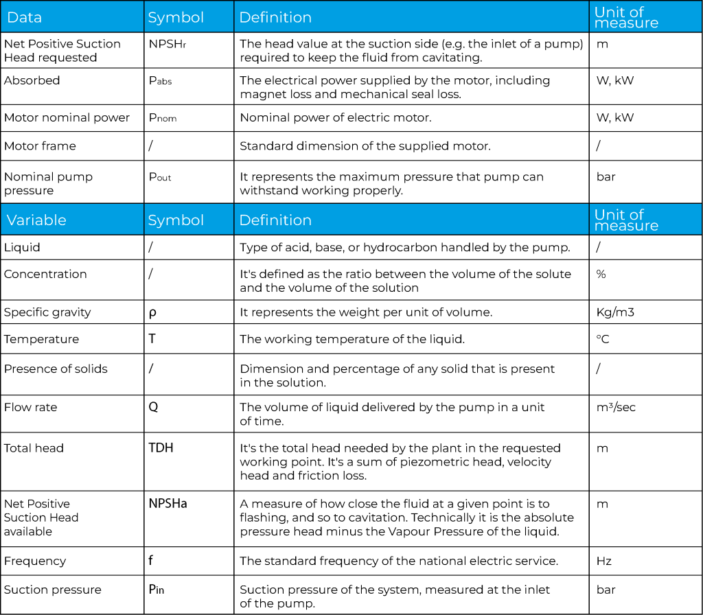
To summarize, all the essential parameters discussed are laid out in the following table. This provides a checklist of the data and variables required for a correct pump selection. It is crucial to accurately define these values to proceed with the identification of the most suitable pump.

how to select a pump - parameters

Conclusion: A data-driven decision

The pump selection process is a meticulous engineering task that requires a thorough analysis of fluid properties, system hydraulics, and environmental conditions. By systematically evaluating each parameter—from chemical compatibility and viscosity to total dynamic head and ATEX requirements—you can ensure the selection of a pump that is not only effective but also highly reliable, energy-efficient, and safe. This data-driven approach goes beyond mere guesswork, guaranteeing a robust solution that will serve your process effectively for years to come.

For expert assistance in analyzing these complex parameters and selecting the ideal pump for your application, contact our team at info@gemmecotti.com. 


Read More
Pressure vs head, what is the difference?

Pressure vs head, what is the difference?

The pump selection of a pump is driven by the following main parameters:
– Head (H)
– Flow rate (Q)
– Fluid characteristics (ρ, γ, T ….)
Sometimes head can be confused with pressure during pump choice. As a matter of fact there is a strict relation between them which is defined by the fluid specific gravity, so the relation is fluid dependent. So what is the difference between pressure and head?

Definition of head and pressure

Head is the height given by the pump to the fluid and it is measured in meters of liquid column [m.l.c.] or simply indicated in meters [m]. The given head is fluid independent: different fluids
with different specific gravities are all lifted at the same height.
Pressure, instead, is fluid dependent and it is affected by the liquid density. In fact the force of a fixed height liquid column over a unitary area will change with different specific gravities. So in this case the same head generates different pressures.

Measurements: Pressure or Head?

Head is not directly measured. Manometers on the pump suction and delivery line give the measure of the pressure. Measurements given by manometers indicate differential pressures imposed by the pump between suction and discharge. These measures are read in [bar] [atm] [psi] [ft H2O] etc.. Specific gravity γ has to be considered to evaluate the correspondent head.

Conversions & Practical Example

As stated before, the same pump at the same working point will give always the same head with different pressures in accordance with the density γ of the working fluid.
For example, a mag drive centrifugal pump HTM 10 working at a given point Q= 7.5 m3/h H = 10 mlc operating with water and concentrated H2SO4 gives the same head (H=10m) to water ( γ= 1kg/dm3) and to sulfuric acid (γ = 1.8kg/dm3), while measurements of differential pressures between suction and delivery will be:

equazione pressione 12

The mathematical relationship is reported in the following equation:

equazione pressione 1
Also power consumption is influenced by the previous relationship of pressure, as:

equazione pressione 2curve pressure

Pressure vs head, what is the difference?

Notes for technicians

– Previous relations are valid for low viscosity fluids (water equivalent), along with increasing viscosity, pump performances have to be reduced using pump derating rules.
– At a fixed rotational speed a centrifugal pump generates head related to the flow rate following its characteristic curve.
– The computation of the needed head that should be delivered by the pump, is not so straight as the evaluation of the desired height difference. Needed Head is composed by the following terms:

  • Geodetic head: difference between suction and delivery height expressed in meters of liquid column

equazione pressione 3

  • Difference between absolute pressure of the delivery and suction reservoir

equazione pressione 4

  • Distributed and concentrated friction losses also expressed in m.l.c.
    equazione pressione 5
Read More
How to read a pump curve

How to read a pump curve

If you are new in the pump field, reading a pump performance curve (usually just called “pump curve”) can be difficult and sometimes confusing. That’s why we want to help you by offering a simple guide for a first approach to a pump curve.

What is a pump performance curve and why do you need to know how to read it?

A pump curve is a graphical representation of the performance of a pump based on the tests of the pump manufacturer. Every pump has its own curve and it varies very widely from pump to pump. The variation depends on many factors such as the kind of pump (centrifugal pump, turbine pump, vane pump etc.), size and shape of the impeller. Pump curves can be used to provide many information of pump performance and absorbed power which are important for a user to determine the working point and motor power and size.

What information can I find on a pump curve?

1- In the simplest and widely used pump curve (commercial multi-pump curve) you can see two vital pump performance factors: flow and head.

The flow or capacity (Q) is measured in m3/second according to the international standards but usually you can find it expressed in m3/h, l/min or gpm (in the US). It is the volume of liquid moved in an amount of time. On the curve below (Picture 1) you can see the flow marked in red on the horizontal axis.

The head (H) is the height at which a pump can raise a liquid up. It is measured in meters (m or mlc meter of liquid column) or feet and you can see it marked in blue on the vertical axis on the picture below.

Pump performance curve with flow and head

PICTURE 1 MULTI-PUMP CURVE 

How can you read this pump curve?

To select the right pump model you should, first of all, identify the capacity and the head needed for  your system.

If you need for example a flow of 15 m3/h at 20 m you can find the right pump curve and consequently the right pump in the intersection of the two red arrows in the chart. In the example below the pump suitable is magnetic drive centrifugal pump model HTM 31.


How to read a pump curve


The curve enables you to see how the pump will perform at any given point within its performance range. For example, the same pump model HTM 31 at 15 m3/h will produce a head of 20 m, or at 24 m of head the pump will generate a flow of 8 m3/h.

Once you have chosen the right pump type whether centrifugal, turbine, vane or any other, you can study in details the specific curve of the selected pump model with other technical information.

2– In picture 2 you can see an example of a centrifugal pump curve (HTM 31 PP/PVDF) with additional details than curve in picture 1 such as for example the impeller diameter (curve A circled in red), the NPSHr (curve B) and the absorbed power (curve C). In some case you can also find the pump efficiency.  This kind of curve is usually used by pump manufacturers to select the correct pump model among their set of performance curves.

Performance curve centrifugal pump

PICTURE 2

How can you read this pump curve?

In the title box at the top you can find the pump model, the number of poles of the motor, the frequency, the RPM and the pump material (selected according to the liquid to pump).

In curve A you can see the flow and head as described in the paragraph above but there is also a reference of the impeller diameter. For this pump model the available impeller diameters vary from a  minimum of   110mm to a maximum of 134 mm. The impeller would be trimmed by the manufacturer to whatever diameter needed to meet your conditions of service. If the impeller selection is 122 mm at a flow of 10 m3/h the head is about 19 mlc. The manufacturer would determine the proper impeller diameter for your conditions and trim it to the correct diameter.

Curve A - centrifugal pump

In curve B you can see the NPSHr of the pump measured in meters or feet in accordance with the capacity required. This is the minimum head at the suction of the pump that allows the pump to work properly. If sufficient NPSH available is not supplied by the plant (NPSHa) the pump will cavitate and this will affect both the performance and the pump lifetime. In case of 10m3/h capacity you have to find the intersection with the curve of the selected impeller diameter and read the value on the left.

Curve B - centrifugal pump

In curve C you can find  the absorbed power required for pumping a liquid with a SG of 1. Once determined the impeller diameter and the flow you can find the intersection where you can read the absorbed power, which is necessary to determine the relevant motor power.

Curve C - centrifugal pump

The correct selection of a pump using a pump curve is essential to permit a proper working of your system. A working point too far out on the curve, or too far back, can cause damage to the pump, excessive energy consumption, poor performance and pump failure.

For further information don’t hesitate to contact us www.gemmecotti.com


Read More
Newsletter