If you are new in the pump field, reading a pump performance curve (usually just called “pump curve”) can be difficult and sometimes confusing. That’s why we want to help you by offering a simple guide for a first approach to a pump curve.
What is a pump performance curve and why do you need to know how to read it?
A pump curve is a graphical representation of the performance of a pump based on the tests of the pump manufacturer. Every pump has its own curve and it varies very widely from pump to pump. The variation depends on many factors such as the kind of pump (centrifugal pump, turbine pump, vane pump etc.), size and shape of the impeller. Pump curves can be used to provide many information of pump performance and absorbed power which are important for a user to determine the working point and motor power and size.
What information can I find on a pump curve?
1- In the simplest and widely used pump curve (commercial multi-pump curve) you can see two vital pump performance factors: flow and head.
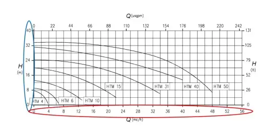
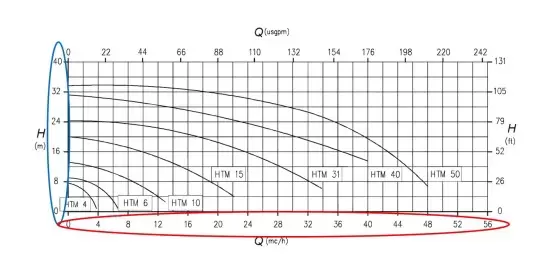
The flow or capacity (Q) is measured in m3/second according to the international standards but usually you can find it expressed in m3/h, l/min or gpm (in the US). It is the volume of liquid moved in an amount of time. On the curve below (Picture 1) you can see the flow marked in red on the horizontal axis.
The head (H) is the height at which a pump can raise a liquid up. It is measured in meters (m or mlc meter of liquid column) or feet and you can see it marked in blue on the vertical axis on the picture below.
PICTURE 1 MULTI-PUMP CURVE
How can you read this pump curve?
To select the right pump model you should, first of all, identify the capacity and the head needed for your system.
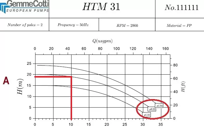
If you need for example a flow of 15 m3/h at 20 m you can find the right pump curve and consequently the right pump in the intersection of the two red arrows in the chart. In the example below the pump suitable is magnetic drive centrifugal pump model HTM 31.
The curve enables you to see how the pump will perform at any given point within its performance range. For example, the same pump model HTM 31 at 15 m3/h will produce a head of 20 m, or at 24 m of head the pump will generate a flow of 8 m3/h.
Once you have chosen the right pump type whether centrifugal, turbine, vane or any other, you can study in details the specific curve of the selected pump model with other technical information.
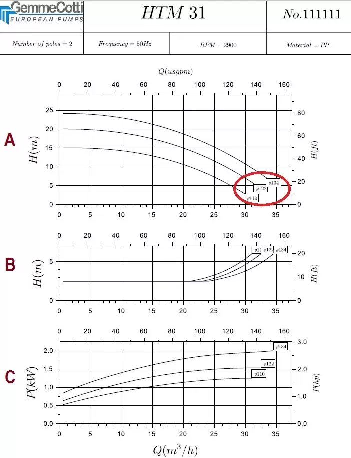
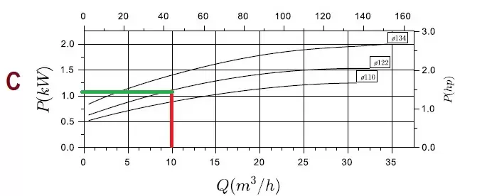
2– In picture 2 you can see an example of a centrifugal pump curve (HTM 31 PP/PVDF) with additional details than curve in picture 1 such as for example the impeller diameter (curve A circled in red), the NPSHr (curve B) and the absorbed power (curve C). In some case you can also find the pump efficiency. This kind of curve is usually used by pump manufacturers to select the correct pump model among their set of performance curves.
PICTURE 2
How can you read this pump curve?
In the title box at the top you can find the pump model, the number of poles of the motor, the frequency, the RPM and the pump material (selected according to the liquid to pump).
In curve A you can see the flow and head as described in the paragraph above but there is also a reference of the impeller diameter. For this pump model the available impeller diameters vary from a minimum of 110mm to a maximum of 134 mm. The impeller would be trimmed by the manufacturer to whatever diameter needed to meet your conditions of service. If the impeller selection is 122 mm at a flow of 10 m3/h the head is about 19 mlc. The manufacturer would determine the proper impeller diameter for your conditions and trim it to the correct diameter.
In curve B you can see the NPSHr of the pump measured in meters or feet in accordance with the capacity required. This is the minimum head at the suction of the pump that allows the pump to work properly. If sufficient NPSH available is not supplied by the plant (NPSHa) the pump will cavitate and this will affect both the performance and the pump lifetime. In case of 10m3/h capacity you have to find the intersection with the curve of the selected impeller diameter and read the value on the left.
In curve C you can find the absorbed power required for pumping a liquid with a SG of 1. Once determined the impeller diameter and the flow you can find the intersection where you can read the absorbed power, which is necessary to determine the relevant motor power.
The correct selection of a pump using a pump curve is essential to permit a proper working of your system. A working point too far out on the curve, or too far back, can cause damage to the pump, excessive energy consumption, poor performance and pump failure.
For further information don’t hesitate to contact us www.gemmecotti.com

